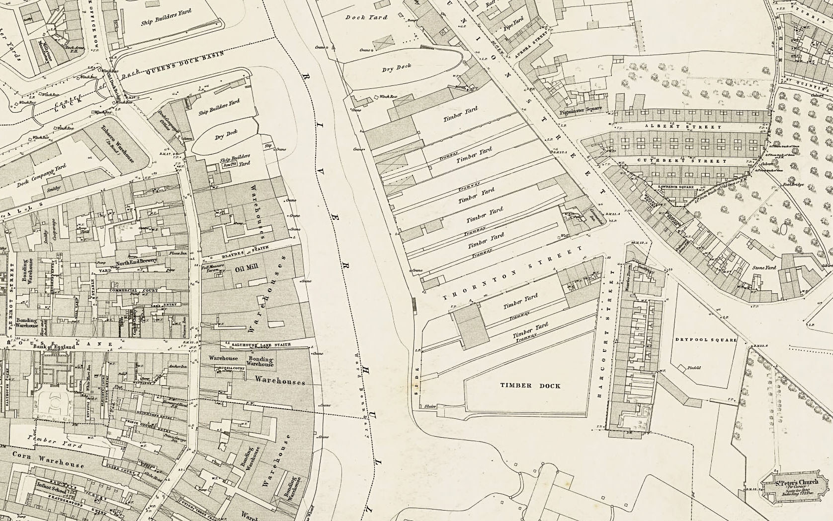
The original bridge linking west and east Hull at Drypool was also known as Salthouse Lane Bridge. The article below, along with the engravings, is the original report as it was published in the Engineer, in London on the evening of Friday 3rd January 1890. The map of the bridge site prior to its development is from 1853 and is published here with the permission of the National Library of Scotland.
THE DRYPOOL BRIDGE, HULL.
This bridge crosses the river Hull and connects the Old Town and the East District of Hull, is known as the Drypool Bridge, and was sanctioned by the Hull (Drypool) Bridge and Improvement Act, 1885; an Act obtained by the Corporation after a severe and expensive Parliamentary contest. The width of the river where the bridge has been constructed is 180ft., and the total length of the bridge 197ft.
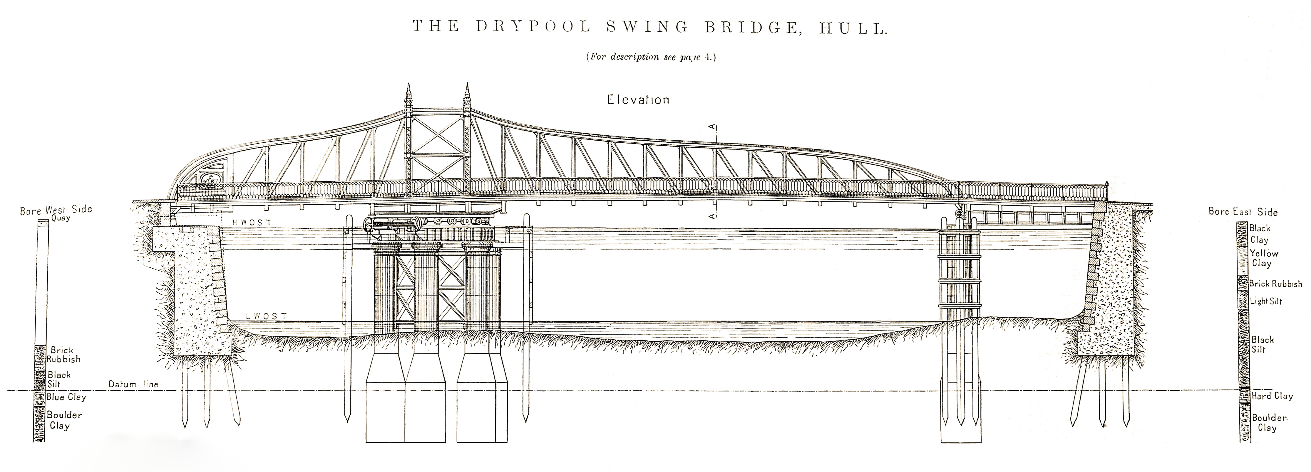
Of this length a short portion at the east end is fixed, and the remainder movable, swinging on a turntable supported by six cylinders, sunk into the bed of the river to the west of the main channel. Two additional cylinders, standing to the east of the channel, carry the west end of the fixed portion, and also support one arm of the movable portion when the bridge is open for road traffic.
Short lengths of river wall have been constructed at the ends of the bridge. These walls are composed of cement concrete, 6 to 1, faced with Bramley Fall ashlar; and are carried upon piles, 15ft. long, driven 4ft. into the boulder clay, or to a depth of about 40ft. below high-water level.

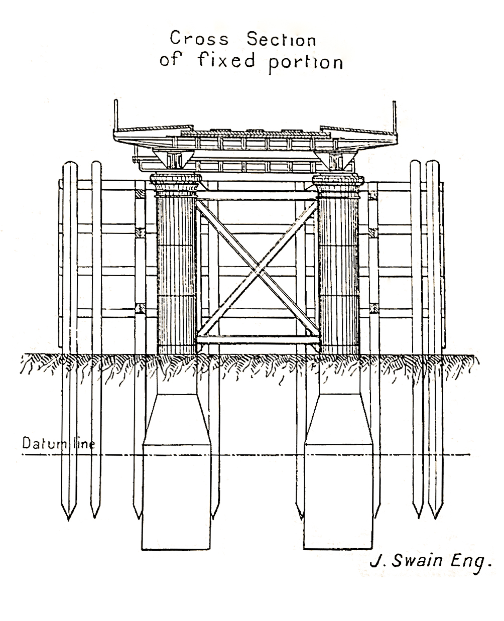
The cylinders are of cast iron, 8ft. diameter at the base, diminishing to 5ft. at a height of 18ft. above the base; and were sunk in the usual way, by excavating from the inside and weighting on the top, to a depth of 45ft. below high-water, or about 20ft. below the bed of the river. When sunk they were filled with cement concrete, 5 to 1, and each tested with a load of 200 tons. The six main cylinders carry heavy cast iron girders, over which works the turntable, consisting of twenty-one turned cast steel rollers, 2ft. diameter, tied in by wrought iron radius rods to a central pivot, and running upon a turned cast steel roller path, fixed to the cast iron girders.
The upper roller path is also of turned cast steel, and is fixed beneath a massive framework of wrought iron girders, carrying the main girders of the bridge. The main girders are ofan open trellis construction, 163ft. 4in. in length, and of a maximum depth of 19ft., and as can be seen from the engravings, their outline is somewhat unusual.
The two arms of the bridge are of unequal length, the long arm over the main channel of the river measuring 108ft. 4in. from the centre of the turntable, and the short arm 55ft., and the difference in the weight of the two is counterbalanced by 140 tons of cast iron stowed at the end of the short arm. The top and bottom booms of the main girders are of inverted trough section, built up of plates and angles; the number of plates, both at the top and sides, varying at different points, to correspond with the varying strains. The vertical and diagonal members are composed of channels, tees, and flat bars of different sections. The end bays of the short arm are cased in to receive counterbalance, and the sides of the casing are ornamented by panels bearing the arms of the Admiral of the Humber.
The main girders are 20ft. apart, centre to centre, and the carriage-way is constructed between them on cross girders, 7ft. 3in. apart, fixed beneath the main girders. The carriage-way is formed of a layer of 6in. grooved and tongued pitch pine planking, laid longitudinally and bolted to the cross girders, and a layer of 3in. creosoted redwood planking, fixed diagonally on the pitch pine. The 3in. planking is caulked and made watertight, and upon it are fixed wrought iron bars for wheel tracks, and elm battens for horse tracks.

Footways are formed, outside the main girders, of 3in. planking, carried on the projecting ends of the cross girders. The extreme width of the bridge is 35ft., and the weight of the movable portion is about 480 tons. The fixed span at the east side of the river is constructed of two plate girders, with cross girders and planking similar to those of the movable portion.
The west approach has been formed chiefly on the site of a warehouse, which was purchased and removed by the Corporation for the purpose. The east approach is formed by a street which previously existed, but which has been raised to meet the level of the bridge. Both approaches have been paved with granite.
The bridge is turned by two hydraulic rams, each 17in. in diameter, and 4ft. 3in. stroke, fixed to the cast iron girders beneath the turntable, and worked by power obtained from the Hull Hydraulic Power Company, at a pressure of 700lb. per square inch. Hand gear is also provided for use in case of emergency.
In closing, the ends of the bridge run up adjustable wedges, and are locked automatically on reaching the proper point. The working levers for the rams and for releasing the locking gear are arranged so as to be controlled by one man standing near the centre of the bridge; and the principal duties of two other men who are in attendance, are to stop the carriage and foot traffic, and to assist vessels in passing.
When the bridge is open for river traffic, a clear waterway of 80ft. exists between the fenders. The bridge is designed to carry a rolling load of 25 tons on four wheels, 7ft. apart longitudinally, and 6ft. apart transversely; together with a load of 40 lb. per square foot on the carriage-way, and 120 lb. per square foot on the footways; and the main span was tested by passing a rolling load of 30 tons over it, while 135 tons of iron were stacked upon it.
The strains upon all portions of the structure were carefully gone into before the preparation of the contract plans. The strains upon every member of the main girders under all possible conditions, were computed by the graphic method; separate series of diagrams being used for—(1) strains due to dead weight while the bridge is swinging: (2) strains due to dead weight and full distributed live load, with the rolling load at various points, while the bridge is supported at the ends; and (3) strains due to dead weight and rolling load, together with various portions of the distributed live load.
The contract plans, thirteen in number, which show almost every part of the work in detail, were lithographed full size, and copies supplied, together with a copy of the specification and quantities, to the contractors who proposed to tender. The ironwork and woodwork of the bridge, and the timber work of the fenders, were executed by Messrs. J. Butler and Co., Stanningley, near Leeds, and the river walls and approaches by Mr. T. B. Mather, Hull. We are indebted to Mr. A. E. White, borough engineer, for the drawings from which our engravings are made.
The cost of the works, exclusive of parliamentary expenses, compensation, and purchase of property, has been as follows: Ironwork, &c., £12,102; river walls and approaches, £5682; other works, £766; total, £18,550.
The works were commenced early in 1887, and the bridge was formally opened in September 1888.

Open Bridges made history in 2017 when for the first and only time, all 13 of the bridges over the River Hull were raised, swung or closed simultaneously to allow a flotilla of vessels to make their way to the Humber to a backing of an especially-composed live music score.
Following Open Bridges, ‘A River Full of Stories’ is an oral history project gathering memories of life and work on and around the River Hull. The book is now available from all Hull & East Riding Libraries and to order from UK libraries and the British Library.
If you’d like to, we’d be pleased if you’d subscribe to our blog, it’s free and you can do so here: