
The New North Bridge Monday 10th August, 1931

In 1926 Parliament gave the go-ahead for the construction of a new four track bridge to be built on the straight line of a new street from Charlotte Street to Witham. The new street was called George Street.

George Street, Charlotte Street and North Bridge, 14th May, 1933
FRom the Opening Day Souvenir Programme
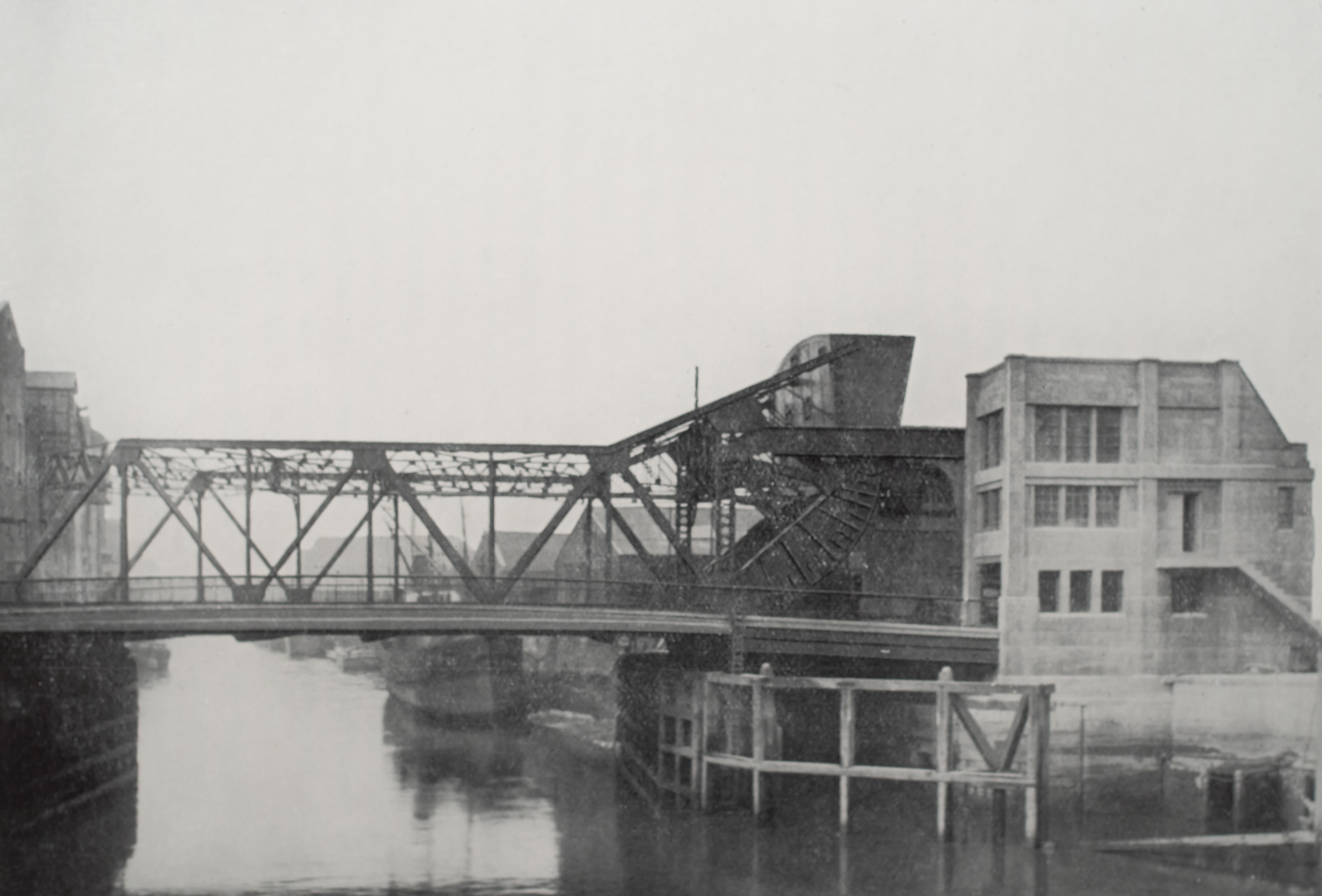
“The New Bridge is of the Scherzer type of bascule. The back end of the opening leaf is formed of two rockers of about a quarter circle, 20 ft. in radius. On these rockers the bridge rolls back on two track girders at road level for about 28 ft., the angle of extreme elevation being about 81°.
A large overhead ballast tank is attached to the rear end of the rockers and main trusses and filled with concrete sufficient to balance the bridge over the point of contact with the track girders. The total rolling weight is 950 tons, of which about 600 is ballast.
The track girders are supported at the ends on four cylinders sunk in the riverbed. The bridge is drawn back by horizontal arms attached at the centre of the quadrant circle. The arms are provided with toothed racks on the underside engaging with pinions projecting from the machinery houses.
The opening span is 88 ft. 6 in. over all steelwork. The bridge crosses the river at an angle of about 80°. This diminishes the effective waterway to 65 ft. clear between fenders. The bridge is 70 ft. total width between handrails, the roadway is 38 ft. 6 in. wide, and cantilevered footpaths 12 ft. wide are provided outside each main girder.
Road gates are not provided. Traffic is controlled by chains drawn across the road as in other Hull bridges. The operations of securing and releasing the chains are electrically interlocked with the operations of opening and closing the Bridge.
The track girders are supported on four cylinders founded about 20 ft. below the river bed on a hard marl bed. The lower portion of the cylinder is 20 ft. diameter 10 ft. deep, built of steel plate and internally braced. Above this is a steel plate cone section 10 ft. deep tapering from 20 ft. to 9 ft. diameter. Above the cone are cylindrical C. I. rings, 9 ft. diameter, 5 ft. deep, three in number, and a making up piece at the top. The cylinders were erected complete upon a timber stage 2 or 3 ft. above the river bed. A massive cross beam was erected over the cylinder and Weston blocks hooked to temporary baulks inside the cylinder, which was then lifted a few inches, the timber platforms withdrawn from beneath and the cylinder lowered on to the river bed. Concrete was placed inside the cylinder to weight it, a vertical passage 5 ft. diameter being left down the centre. The top was closed by a heavy steel plate attached to which was a simple air lock providing space for one man in a sitting position. The outer door was in the steel plate and closed by a circular manhole cover. The inner door was in the vertical side of the. The inner door was in the vertical side of the air lock and was rectangular. Four men were employed inside the cylinder on the excavation of the bottom which was removed by a 1 ¼ cu. ft. bucket through the air lock. Air pressure was used up to about 10 lbs. per square inch, and no obstacles or troubles were experienced during the sinking to the marl. The cylinders were finally concreted up solid inside.
The operating arms for drawing the bridge back are of box section built up of steel plates with a cast steel toothed rack on the bottom, the teeth of which are 6 in. pitch x 18 in. face. Each arm is 40 feet long over all, and weighs 15 tons. The main pinions engaging with the racks are 42 in. diameter forged solid with the shaft which is 17 in. diameter in the main bearings. The pinions project from the inner walls of the two machinery houses. Inside each house there is a first reduction gear of cast steel spur and pinion, then a worm gear reduction, the worm shaft being horizontal and parallel to the road. The worm is solid forged on the steel shaft, the worm wheel rim is phosphor bronze. The next reduction is a spiral gear the shaft of which extends across the roadway, and connects the two sets of gearing together. This shaft is housed in a transverse portal bridge over the roadway in the centre of which are placed the last spur reduction gears and the motors, which are two in number rated at 75 B.H.P. each. The nose end of the bridge is locked by a pair of locking bolts actuated through rack and pinion gear by a 3 B.H.P. motor.
The estimated amount of current required to raise the bridge against a maximum wind pressure of 20 lbs. per square foot is 4.6 units: at 2d. this amounts to 9.2d.; allowing one-third of this for closing with wind in favour, the total cost for complete cycle will be 1/- maximum. In the absence of wind pressure the h.p. required will be a very small fraction, probably not 25 per cent. of the full 150 h.p. The cost of operation would probably be 1d. as a minimum.
The machinery is placed in two houses built over the footpaths and connected across the road by an overhead portal bridge. The head room over the footpath is about 8 ft. and over the roadway about 18 ft. 6 in. The main walls of the machinery house are 2 ft. 3 in. thick, and are heavily reinforced to withstand the pull of the operating arms. The rear ends of the walls are connected to a R.C. ballast box below the road level, filled in with earth to resist the overturning pull of the operating arms. The whole structure is monolithic, and carried down to ordnance datum-i.e., about 18 ft. below road level-and is supported on about 50 pitch pine piles. The roadway is supported on a R.C. floor, which in turn is supported on R.C. columns on a basement floor about 8 ft. lower. This rests on deep beams partly embedded in excavated ground, and supported at the front ends by the river wall.
The two outer main cylinders are connected together by a strongly braced steel structure. This is protected by a system of piles and horizontal fenders. Distance blocks of timber are fitted between the fendering and steel work at suitable points to distribute shock from vessels bumping the fenders.
The Foredyke stream, discharging into the River Hull diagonally across the east approach to the bridge, is taken under the road in a double concrete culvert about 100 ft. long from the existing bridge at Lime Street to the outfall. The culverts are box section 11 ft. 6 in. square.
At Lime Street Bridge the existing gates were in two pairs. The south half of the new culvert was built first, leaving the north pair of gates free to discharge outside the dam, behind which all of the south culvert was constructed. Before removing the dam the south pair of gates were removed from their old position and re-erected at the new outfall. The dam was then removed and redriven for the construction of the northern half, and the south culvert opened to the stream. The northern half of the culvert was constructed in a similar manner, after which the machinery houses were completed and the machinery installed.
The estimated cost of the bridge works, offices, Foredyke culverts, road approaches, removal of old bridge, and making good river walls is £103,500. The estimated cost of property and expropriation is £155,000. The total estimated cost is £258,500.
The operations of lifting and lowering the bridge have been made as fool-proof as possible. The sequence of operations is as follows:-
To open the bridge for a vessel to pass, the Bridge Master presses a button in the Machinery House, causing an electric gong to ring as a warning to road users and pedestrians that the bridge is about to be opened. This gong continues to ring until the bridgemen, one on each side of the river, open the doors fixed in the chain-posts. The opening of these doors automatically operates three switches which
(1) Prevent any movement of trams within 50 feet of the bridge on either side by causing the trolley wires to become dead.
(2) Stop the ringing of the gong.
(3) Light a lamp in the control room shewing the operator that the bridgemen are about to withdraw the chains from the posts.
(4) Light a red stop signal on the tram standard nearest the bridge on the left hand side of each approach.
The bridgemen then draw the chains across the road, and stop all traffic. On opening the doors in the chain posts on the opposite side of the road, a switch is operated which allows the small motor to the nose and locking bolts to be started. Fixed in these chain posts are also switches with bell cranked handles, and these are pulled forward by the bridgemen to a catch and held there by pins attached to the ends of the chains. The pulling forward of these switches lights a lamp in the control room, indicating that the chains are safely across the road, and the bridge may now be lifted.
To open the bridge the operator moves the controller to the first notch. This actuates the small 3-h.p. motor, fixed in a chamber under roadway at the nose end and withdraws the locking bolts. These bolts, as, they travel backwards, themselves operate two switches, the first to light a lamp to indicate when they are completely withdrawn, and the second to enable the main motors to be energised. The operator next moves the controller to the second notch, which releases the brakes, then to the third notch and the bridge begins slowly to lift. Finally, when the controller is moved to the fourth notch, the bridge lifts at the maximum working speed. As the bridge approaches the fully opened position, a limit switch causes the motors to drop to a creeping speed and, finally, to stop altogether. Should it be necessary only partially to open the bridge to give the requisite clearance for a passing vessel, the operator can stop the bridge in any desired position during its ascent.
The foregoing sequence of operations is reversed in lowering the bridge except that when the bridge is within 5 degrees of the rest blocks at the nose end, the motors and the bridge are automatically stopped by means of a limit switch, and the operator controls the remaining descent by a foot pedal, thus bringing the bridge gently to rest on the blocks. The bridge itself, on finally closing, operates switches which energise the small motor to close the locking bolts and also light a lamp in the control room to indicate that the bridge is completely closed and locked. The bridgemen are then able to draw the chains from the posts, cross the road, wind the chains in the posts on the other side and traffic may proceed.
A change gear arrangement allows the bridge to be operated at two speeds. The normal time for a complete opening or closing is one-and- three-quarter minutes. During a strong wind the low gear will be used requiring two-and-a-half minutes to open or close. In the event of complete failure of the electric current, hand gear has been provided and the bridge can be raised or lowered by eight men in about 80 minutes.”
Mr. T. Thomas, the late City Engineer, was responsible for the design of the Bridge and Mr. T. Somerscales has acted as Bridge Engineer during the period of construction.

Photographs from the Sounvenir Programme

George Street and North Bridge 14th May 1933
Rich and Lou Duffy-Howard
If you’ve enjoyed the post, we’d be delighted if you’d subscribe to our blog. It’s free and you can do so by entering your email below: