
This page has been transcribed from the published minutes and meeting of the Institution of Mechanical Engineers chaired by William Armstrong in 1869. Sir William describes his hydraulic design and construction of the brand new railway swing bridge built over the River Ouse at Goole for North Eastern Railways’ network link to Hull. I’ve transcribed the proceedings in full and restored all of the original plates of the bridge, published here. You can click on the images to enlarge the plans to have a closer look.
The Institution of Mechanical Engineers Proceedings 1869
Published by the Institution, 81 Newhall Street, Birmingham

DESCRIPTION OF THE HYDRAULIC SWING BRIDGE FOR THE NORTH EASTERN RAILWAY OVER THE RIVER OUSE NEAR GOOLE.
By Sir WILLIAM G. ARMSTRONG, President.
The formation of the Hull and Doncaster section of the North Eastern Railway necessitated crossing the river Ouse by an opening bridge, so as to admit the passage of the important traffic carried on the river in large sailing vessels. It was also necessary that there should be not more than one pier in the navigable channel, with a clear opening of not less than 100 feet on each side. The requirements of the railway and river traffic necessitated a construction of bridge admitting of being opened and closed very rapidly; and it was also requisite that the power applied should be capable of controlling with great accuracy the momentum of so ponderous a mass. Under these circumstances the bridge described in the present paper was designed by Mr. Harrison, the Engineer of the Railway, with a view to the application of hydraulic pressure as the moving agent.
The instances in which hydraulic power had previously been applied to the opening and closing of movable bridges are very numerous, amounting to upwards of fifty examples. Most of these bridges have been erected for the passage of railway traffic, both on main lines and branches; and they may be divided into three classes.
1st. Swing bridges in which the bridge is lifted from its solid bearings by a central press, previously to being turned round by hydraulic power.
2nd. Swing bridges in which the bridge rests upon a circle of live rollers and is turned by water pressure without being lifted.
3rd. Draw bridges, in which the movable platform is drawn back and pushed forwards again in the line of the roadway by means of hydraulic machinery.
There is also one example of a bridge worked by hydraulic power on the “bascule” plan of the old lifting draw-bridges; this is at Liverpool over one of the dock entrances.
The first hydraulic swing-bridge was erected in 1852 over the river Severn on the Gloucester and Dean Forest Railway; and the first hydraulic draw-bridge was erected in 1853 over the river Tovey on the South Wales Railway near Carmarthen.
All the swing bridges which turn on a centre pier, and span an opening on each side, have been made to turn on live rollers without being lifted, because in bridges of that construction neither extremity can have any steadying support in the act of turning; but in some instances a central press has been applied to relieve the rollers of part of the weight. Where single-leaf swing-bridges are lifted by a central press, the deflection of the overhanging end is taken off by letting the bridge down upon its solid bearings when closed; but in the case of draw-bridges, and swing-bridges not lifted by a central press, hydraulic machinery is applied to lift the overhanging end or ends, so as to take off their deflection after closing. The openings crossed by these several forms of bridges have varied from 30 to 100 feet span. The heaviest bridge to which the central lifting arrangement has been applied is one over the Regent’s Canal near the London Docks, in which instance the weight lifted and turned amounts to 450 tons. In bridges with the central press, the head of the lifting ram fits into an inverted cup upon the bridge, in order to allow for a slight oscillating movement; and the bridge in swinging turns upon the water in the press by carrying the ram round with it. The pressure of water employed in the central hydraulic press is about 800 lbs. per square inch, and in the largest of these bridges the diameter of the ram turning upon the water is 51 inches.
In most cases the hydraulic bridges are in connection with a system of water pressure applied to cranes and other machines in the vicinity, the pressure being supplied in the usual manner by steam engines pumping into accumulators. But in some few instances where there is not such a supply of power at hand, the pressure is supplied by hand pumps charging the accumulator, and thus storing up the power ready for application whenever required. At the Ouse Bridge there was no supply of hydraulic power at hand, and in that instance the total power required was too large to be supplied by hand labour. It was further necessary, on account of the position of the swing bridge, either to convey the power to the centre pier by a pipe under the bed of the river, or to produce it upon the pier by placing a steam engine within the pier itself; and the latter plan was the one adopted.
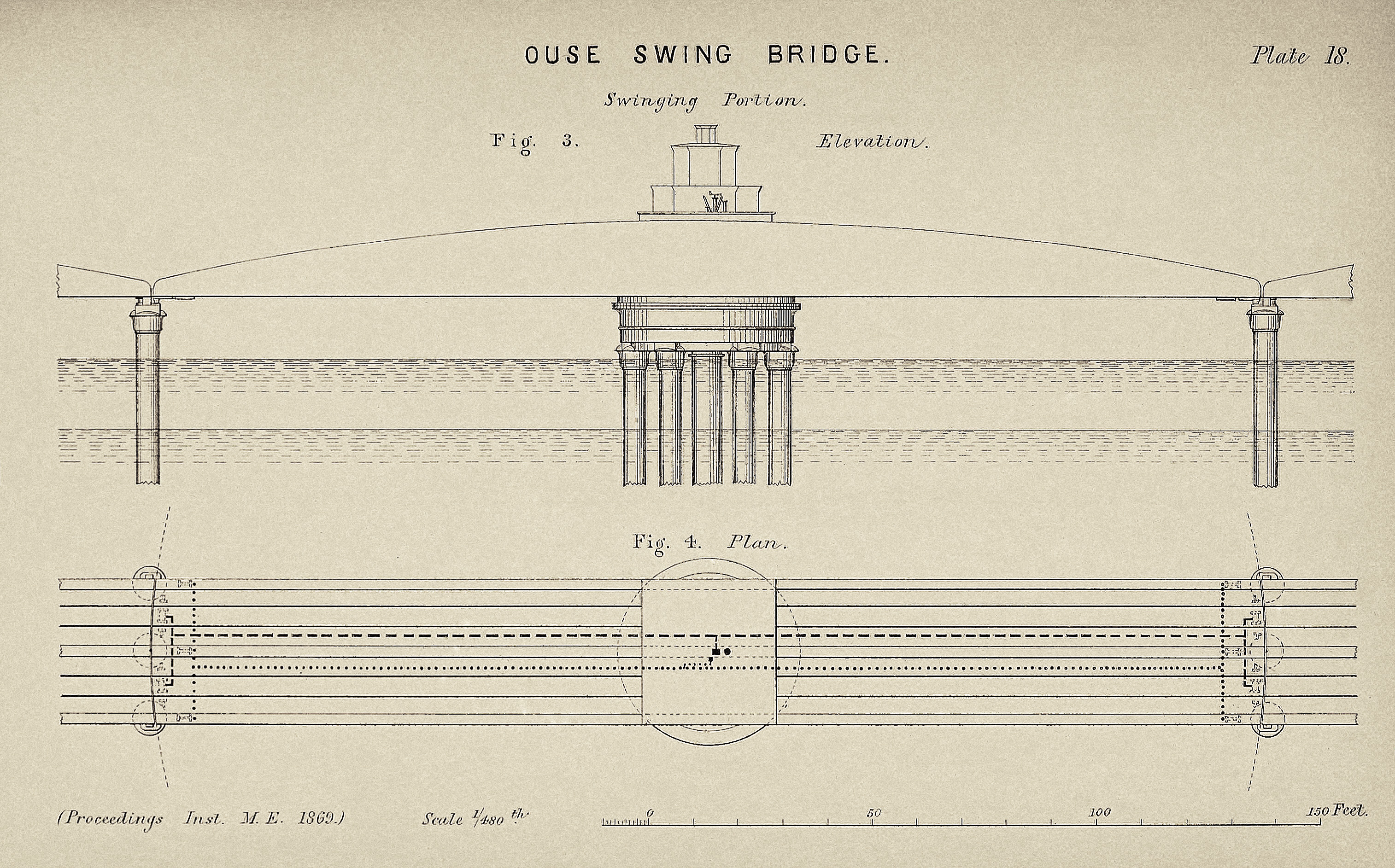
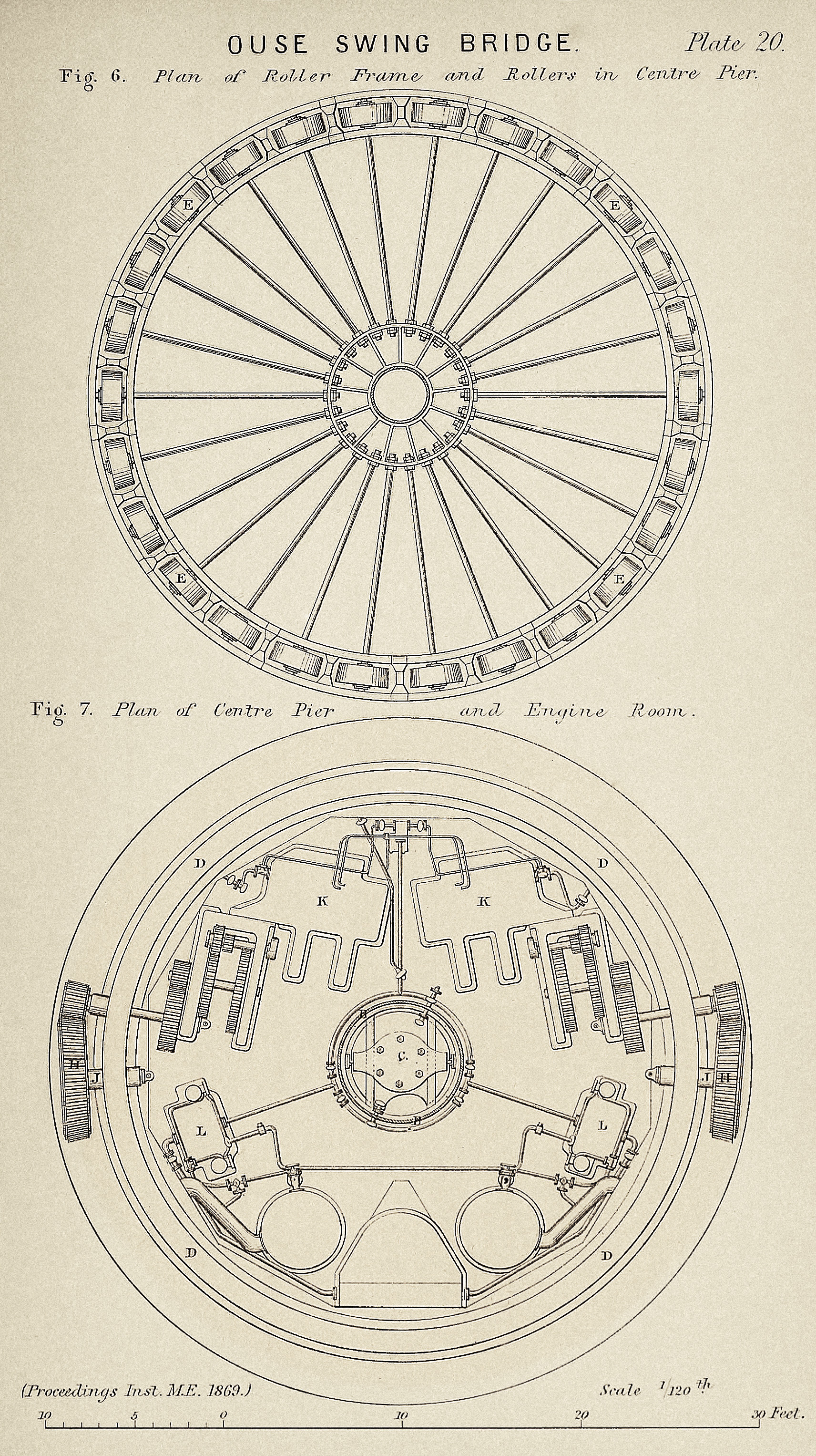
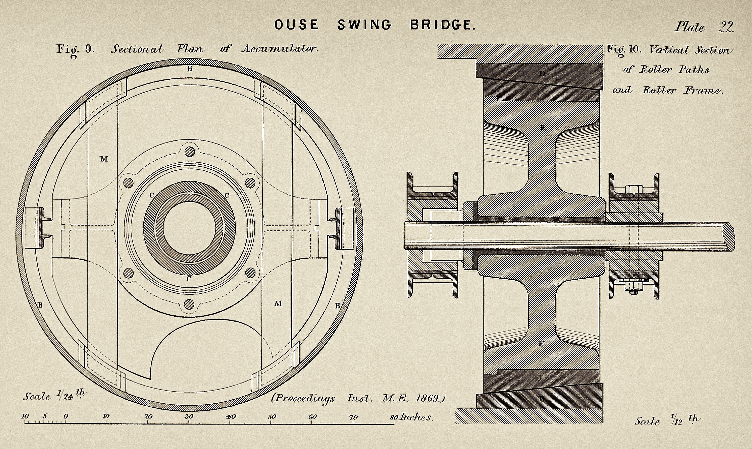
The construction of the Ouse Bridge is shown in Plates 17 to 24. Figs. 1 and 2 are a general elevation and plan of the entire bridge, and Figs. 3 and 4 show an elevation and plan of the swinging portion to a larger scale. Fig. 5 is a vertical transverse section at the centre pier, showing the engine-room and accumulator which are situated within the centre pier; and Fig. 7 is a plan of the centre pier at the level of the engine-room, showing the arrangement of the driving gear with the steam engines and hydraulic engines. Fig. 8 is an enlarged section of one half of the engine-room, and Fig. 9 a sectional plan of the accumulator. Figs. 11 and 12 are a plan and elevation of the hydraulic engines for turning the bridge; and Figs. 13 to 16 show the gear at the two extremities of the bridge for working the adjusting supports and the locking bolts.

The total length of the bridge, fixed and movable, is 830 feet. The fixed portions consist of five spans of 116 feet each from centre to centre of piers, Figs. 1 and 2, Plate 17. The bridge being for a double line of railway, each span is composed of three wrought-iron plate girders, the centre girder having a larger section to adapt it for its greater load; these girders have single webs and are 9 feet deep in the centre. The total width of the bridge from outside to outside is 31 feet. Each of the piers for the fixed spans consists of three cast-iron cylinders of 7 feet diameter and about 90 feet length. The depth from the underside of the bridge to the bed of the channel in the deepest part is about 61 feet. The headway beneath the bridge is 14 ft. 6 ins. from high water datum and 30 ft. 6 ins. from low water.
The swinging portion of the bridge, Figs. 3 and 4, Plate 18, consists of three main wrought-iron girders, 250 feet long and 16 ft. 6 ins. deep at the centre, diminishing to 4 feet deep at the ends. The centre girder is of larger sectional area than the side girders, and instead of being a single web is a box-girder 2 ft. 6 ins. in width, Fig. 8, with web plates 7-16ths to 5-16ths inch in thickness, and the top and bottom booms contain together about 132 square inches section. The roadway is carried upon transverse wrought-iron girders resting upon the bottom flanges of the main girders. Figs. 8 and 14. In the centre of the bridge the main girders are stayed by three transverse wrought-iron frames securely fixing them together and over the top of these frames a floor is laid, from which the bridgeman controls the movements of the bridge.
An annular box-girder A A, 32 feet mean diameter, is situated below the centre of the bridge and forms the cap of the centre pier, Figs. 5 and 8, Plates 19 and 21; this girder is 3 ft. 2 ins. in depth and 3 feet in width, and rests upon the top of six cast-iron columns, each 7 feet diameter, which are arranged in a circle and form the centre pier of the bridge. Each of these columns has a total length of 90 feet, being sunk about 29 feet deep in the bed of the river. A centre column B B, 7 feet diameter, is securely braced to the six other columns by a set of cast-iron stays, which support the floor of the engine-room. This centre column contains the accumulator C, Fig. 5, and forms the centre pivot for the rotation of the bridge.
The weight of the swing bridge is 670 tons. There is no central lifting press, and the entire weight rests upon a circle of conical live rollers E E, Figs. 5 and 8. These are 26 in number, as shown in the plan, Fig. 6, Plate 20; they are each 3 feet diameter with 14 inches width of tread, as shown in Fig. 10, and are made of cast iron hooped with steel. They run between the two circular roller paths D D, 32 feet diameter and 15 inches broad, which are made of cast iron faced with steel; the axles of the rollers are horizontal, and the two roller paths are turned to the same bevil.
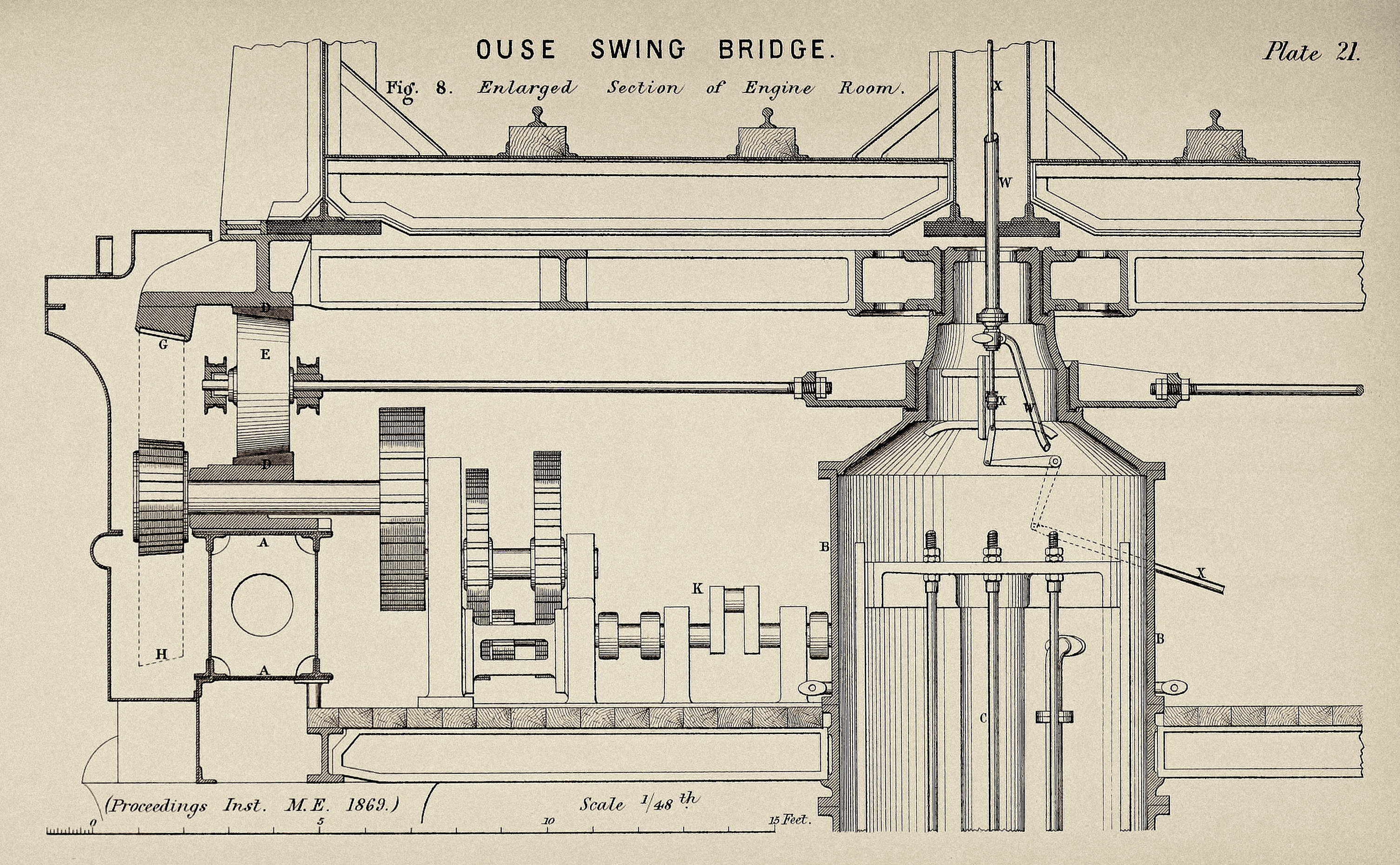
The turning motion is communicated to the bridge by means of a circular cast-iron rack G, Fig. 8, 12½ inches wide on the face and 6½ inches pitch, which is shrouded to the pitch line and is bolted to the outer circumference of the upper roller path. The rack gears with a vertical bevil wheel H, which is carried by a steel centre pin J supported in the lower roller path; and this wheel is driven by a pinion connected by intermediate gearing with the hydraulic engine. There are two of these engines, duplicates of one another, which are situated at K K in the engine room, Figs. 7 and 8; and either of them is sufficient for turning the bridge, the force required for this purpose being equal to about 10 tons applied at the radius of the roller path. Each hydraulic engine is a three-cylinder oscillating engine, as shown in Figs. 11 and 12, Plate 23, with simple rams of 4¼ inches diameter and 18 inches stroke. These engines work at 40 revolutions per minute with a pressure of water of 700 lbs. per inch, and are estimated at 40 horse power each. The steam engines for supplying the water pressure are also in duplicate, situated at L L, Fig. 7, and are double-cylinder engines driving three-throw pumps of 2¾ inches diameter and 5 inches stroke, which deliver into the accumulator. The steam cylinders are 8 inches diameter and 10 inches stroke, each engine being 12 horse power.
The accumulator C, Fig. 5, shown also in the sectional plan Fig. 9, Plate 22, has a ram 16½ inches diameter with a stroke of 17 feet; it is loaded with a weight of 67 tons, composed of cast-iron segments suspended from a crosshead and working down inside the cylindrical casing formed by the centre cylinder of the pier. A pair of cross beams M M are fixed to limit the rise of the weight.
For the purpose of obtaining a perfectly solid roadway when the bridge is in position for the passage of trains, and also for securing the perfect continuity of the line of rails, the following arrangement is adopted, shown in Figs. 13 to 16, Plate 24. Each extremity of the bridge is lifted slightly by a horizontal hydraulic press N, Figs. 13 and 14, acting upon the levers P P which form a toggle joint; the press has two rams acting in opposite directions upon two toggle-joint levers, which are connected by a horizontal bar Q, and this bar is confined to a vertical movement by a stud sliding in a vertical guide, so as to ensure an exactly parallel action of the two toggle-joint levers, in order thereby to lift the bridge end exactly parallel. While the end of the bridge is thus held lifted, the three resting blocks R R, one under each girder, are pushed home by means of three separate hydraulic cylinders S S, Figs. 15 and 16; the bridge is then let down upon these resting blocks by the withdrawal of the toggle-joint levers PP, and the bridge ends are then perfectly solid for trains to pass over. The hydraulic cylinders N and S for working this fixing gear at the two ends of the bridge are controlled by valves placed upon the centre platform in reach of the bridgeman, the pipes from the valves to the cylinders passing along the side of the roadway of the bridge.


For the purpose of enabling the bridgeman to stop the turning movement of the bridge at the right place, an indicator is provided consisting of a dial with two pointers which are actuated by the motion of the bridge. One of these pointers makes 2 revolutions and the other 42 revolutions for one complete rotation of the bridge; they are similar to the hour and minute hands of a watch, the slower pointer being analogous to the hour hand and the quicker one to the minute hand. The bridge has no stop to its turning movement, and would swing clear past its right position if the turning power were continued; but the bridgeman being guided by the indicator knows when to stop and reverse the hydraulic engines for the purpose of stopping the bridge at its right place. When this is done, a strong locking bolt T, Figs. 13 to 15, 3 inches thick, pressed outwards by a spiral spring, is shot out at each end of the bridge into a corresponding slot in the fixed girder, so as to lock the bridge; and when the bridge is required to be opened these two bolts are withdrawn by a wire cord U, Fig. 15, leading to the platform on which the bridgeman is stationed. In consequence of the line of the bridge lying in a north and south direction, the heat of the sun acting alternately on the opposite sides of the bridge produces a slight lateral warping; and in order to bring the ends back into the straight line after swinging the bridge, so as to enable the two locking bolts to enter their slots, the feet of the toggle-joint lifting levers P P are bevilled off at 55° on their inner faces, as shown at I I in Fig. l4, Plate 24, and bear against corresponding bevils V V on the bedplates. By this means the ends of the bridge when warped are forced back into the correct centre line, in which they are then held secure by the locking bolts.
As the accumulator is stationary in the centre pier, while the fixing gear at the ends of the bridge travels with the bridge in swinging, the communication of water power is effected by a central copper pipe W, Fig. 8, Plate 21, passing up in the axis of the bridge through the middle of the centre girder, and having a swivel joint at the lower end. Also as the bridgeman’s hand-gear rotates with the bridge while the hydraulic turning engines are stationary, the communication for working the valves is made by a central copper rod X, Fig. 8, passing down through the centre of the pressure pipe W in the axis of the bridge. The hydraulic engines are reversed in either direction by the action of a small hydraulic cylinder, which is governed by the movement of a three-port valve actuated by the rod X from the bridgeman’s platform.
The time required for opening or closing the bridge, including the locking of the ends, is only 50 seconds, the average speed of motion of the bridge ends being 4 feet per second. For the purpose of ensuring safety in the working of the railway line over the bridge, a system of self-acting signals is arranged, which is actuated by the fixing gear at the two ends of the bridge; and a signal of all right is shown by a single semaphore and lamp at each end of the fixed part of the bridge; but this cannot be shown until each one of the locking bolts and resting blocks is secure in its proper place.
Mr. R. HODGSON, as Resident Engineer on the Railway, said he had great pleasure in bearing testimony to the admirable manner in which the entire work of the swing bridge now described had been executed; nothing could be more satisfactory than the workmanship in every respect, and although the moving mass was of such remark able size and weight, the movement in turning was so smooth, that not the slightest motion was felt when standing upon the bridge while turning, and with the eyes shut it was impossible to tell that the bridge was moving. All portions of the work were most efficient in every respect, and the report of the Government Railway Inspector stated that the bridge was by far the most perfect and most complete structure of the kind that had ever been erected.
In regard to the construction of the piers supporting the fixed and the movable portions of the bridge, these were constructed of cast-iron cylinders of 7 feet diameter up to low water level, tapering to 5 ft. 6 ins. diameter at high water. A timber staging with guides was erected at each pier for sinking the cylinders in their proper position, and they were sunk through the silt of the river bed by a dead weight placed on each; and on arriving at the water bearing strata the pneumatic process was adopted, with a pressure of air reaching to 36 lbs. per square inch and equivalent to 83 feet head of water. The sinking was carried down by this means till the cylinders rested upon the new red sandstone rock at a depth of 92 feet below the level of the railway, and they were filled up with Portland cement concrete to a height of about 20 feet from the bottom, while the pneumatic pressure was still kept upon them; after which it was taken off, and they were built up solid with brickwork in cement, finishing with a course of granite at the top, upon which the bridge girders rested. After filling the cylinders in solid with the concrete and brickwork, they were tested by being subjected to the pressure of a dead weight; the centre pier, composed of six cylinders, was loaded with 500 tons, and the side piers, composed of three cylinders, were loaded with 250 tons each and in no case were any of the piers found to go down under this testing load more than ½ inch. On the occasion of the testing of the bridge by the Government Inspector, four of the heaviest locomotives were placed on each line of rails, and the deflection did not amount in any of the girders to more than 0.4 inch, which was an unusually small deflection for the span of 116 feet.
Mr. J. RAMSBOTTOM observed that the great work which had been accomplished in spanning so large an opening by the swing bridge now described was one of particular interest to all connected with railways; and the opening and shutting of so large a bridge in so very short a space of time could only be efficiently done by the employment of hydraulic machinery, storing up the requisite power by means of an accumulator charged during the time that the bridge was standing. He enquired whether steel had been used in the construction of the girders, for the purpose of reducing the weight of the moving mass in the swinging portion of the bridge.
The PRESIDENT replied that the girders of the bridge were made of wrought iron, and the only parts where steel had been used were the tyres of the rollers on which the bridge turned, and the facing of the roller paths. There was such entire control over the movements of the bridge by the ample supply of hydraulic power at command, that he did not think the reduction of weight consequent upon the use of steel in the construction of the girders would materially have facilitated the working of the bridge. The magnitude of the parts would certainly have been somewhat reduced by the employment of steel, but the question was mainly one of cost of construction in the first instance.
Mr. H. CHAPMAN enquired what was the amount of steam power employed in charging the accumulator for working the bridge. The PRESIDENT replied that one steam engine of 12 horse power was employed to charge the accumulator, the throttle-valve in the steam pipe being regulated by the rise and fall of the accumulator ram, so that the engine started pumping whenever the accumulator was lowered, and kept the accumulator always charged full, ready for action. A duplicate steam engine was provided, to be ready for use at any time in the event of stoppage of the other engine.
Mr. L. OLRICK mentioned that, for the purpose of confining within a small space the steam power required for charging the accumulator, the pair of boilers used were of the construction known as “Field” boilers, having vertical double water-tubes, and each boiler was only 4½ feet diameter and 6½ feet high, so that they took up very little room in the limited space available within the central pier of the bridge; they had also the advantage of raising steam much more quickly than other constructions of boilers. In the present instance the situation of the boilers did not allow of the usual vertical uptake passing out at the top, and the flue was consequently carried down at the side and continued horizontally to a chimney at the end of the stage adjoining the pier.
Mr. E. A. COWPER observed that the circular girder forming the tipper roller path on the central pier did not appear to be made of such depth and stiffness as the circular girder forming the lower roller path and he enquired whether, during the time that the bridge was standing still with a load on it, this girder was found to be stiff enough to distribute the weight uniformly upon all the rollers round the circle, and prevent the load coming heavier upon those rollers that were immediately underneath the central girder of the bridge.
Mr. WESTMACOTT replied that he had not observed whether there was any deflection in the upper circular girder from the effect of a load on the bridge, and he believed it had sufficient stiffness for distributing the weight equally upon all the rollers. There had not been the means of actually ascertaining the uniformity of weight upon the rollers when the bridge was standing with a load upon it; but in swinging round it was found that all the rollers turned equally, and it was therefore inferred that they all bore a share of the load.
Mr. T. L. GOOCH enquired whether any provision had been made to ensure the working of the hydraulic apparatus in frosty weather. Mr. WESTMACOTT replied that gas jets were provided in the central pier and in the chambers containing the hydraulic cylinders at the ends of the bridge, which would be kept burning in frosty weather to prevent the water from freezing; and the pipes leading to the machinery at the ends of the bridge were enveloped with cinders enclosed in wooden boxes. The gas was supplied from Goole to the south end of the bridge, and was delivered into a storage reservoir composed of elastic bags contained in the bridgeman’s house, from which the supply of gas to the burners was maintained during the time the bridge was open. The two disconnected ends of the gas pipe were each closed during the swinging of the bridge by self-acting valves, which opened inwards into the pipe and were closed by a spiral spring, preventing the escape of the gas; the centre spindle of each valve projected beyond the extremity of the pipe, and the pipe on the swinging portion was made with a telescopic sliding end, which whenever a supply of gas was desired to be taken in was pushed outwards by means of a rod and handle worked from the centre of the bridge, so as to make a tight joint with the end of the stationary pipe and at the same time open the valves.
The PRESIDENT remarked that in the climate of this country hydraulic machinery was in all cases found to be preserved from frost when sunk in the ground only as much as 2 feet depth and covered over with planking. Where the hydraulic cylinders were fixed in chambers, as in the bridge now described, a very small jet of gas kept constantly burning was quite sufficient to exclude the frost. Another expedient, which could be resorted to when no gas could be obtained, had been adopted in the case of the drawbridge on the South Wales Railway over the River Tovey near Carmarthen, by mixing the water of the hydraulic apparatus with common cheap methylated spirit, which entirely prevented freezing; and the same water was used over and over again, so that there was no waste of the spirit.
Mr. I. LOWTHIAN BELL said he had great pleasure in mentioning that the statements which had been made by the resident engineer of the North Eastern Railway, as to the admirable execution of the entire work of the bridge, were fully corroborated by the great satisfaction expressed by the directors at the complete success with which the whole of this remarkable engineering work had been performed, and the great amount of skill displayed in its accomplishment. Even when regarded only in its stationary condition, the magnitude of the bridge was sufficient to stamp it as a structure of importance in railway engineering; and much more was this the case when it was contemplated as a swing bridge, and when the vast weight of so large a moving mass was taken into consideration, together with the perfect control exercised over all its movements by means of the hydraulic apparatus by which it was worked. With regard to the facilities afforded by the hydraulic system for lifting heavy loads, he had now had hydraulic apparatus at work for more than three years at the Clarence Iron Works in the county of Durham, constructed by Sir William Armstrong’s firm, and employed for lifting materials for the blast furnaces at the rate of 2000 tons per day; and after once being started fairly to work, there had never been a single stoppage of the machinery from any defect in the apparatus either in frosty weather or under any other circumstances.
He moved a vote of thanks to the President for his very interesting paper, which was passed. The PRESIDENT said it was highly gratifying to find that the construction of this swing bridge had met with the entire satisfaction of the North Eastern Railway Co., and also that it had afforded the subject for a paper of interest to the Members of the Institution, who would have an opportunity, through the kindness of the North Eastern Railway, of inspecting the bridge and witnessing its performance in working.
Rich and Lou Duffy-Howard
If you’ve enjoyed the post, we’d be delighted if you’d subscribe to our blog, it’s free and you can do so below: