Hull’s River Bridges: Sculcoates, The Engineer, April 1875
This article was published in the Engineer, in London on the evening of April 2nd 1875 and is reproduced here along with the two original engravings. The aerial photographs of the bridge, below the article, are from 1937 and 1947, and the map above is from 1891 and published with the permission of the National Library of Scotland.
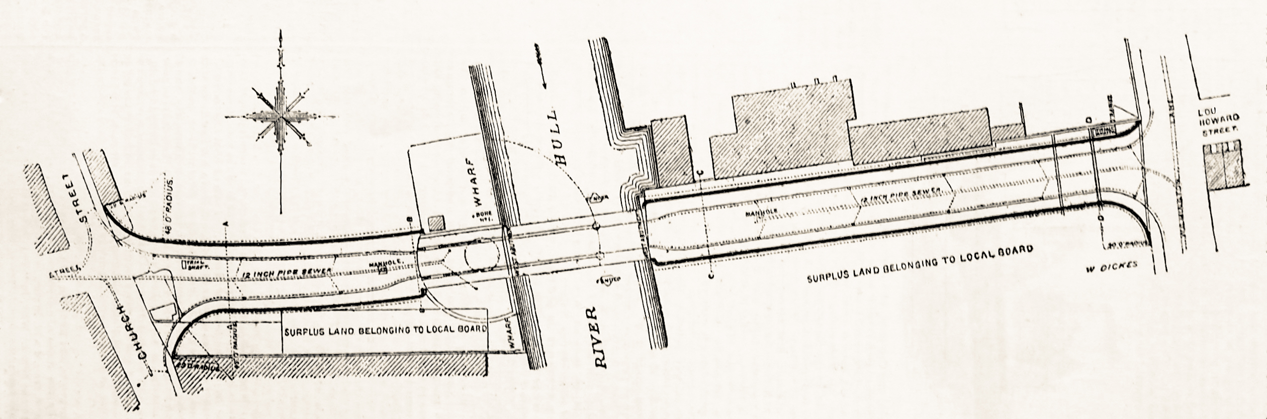
“We give this week the first of two working drawings of the new bridge at Kingston-Upon-Hull, opened to the public by the Mayor and Corporation on the 9th of January.
The bridge is over the river Hull, and is constructed of two spans of 65ft. and 27ft., the wider span being movable for the purposes of Navigation. The appearance of the bridge is light, though at the same time its structure is substantial. The swinging portion of the bridge is formed by two longitudinal plate girders, 113ft. in length, supporting a carriageway between them and footways on canti-levers on each side, and at the tail end of each girder a cast iron counterbalance box of ornamental design is constructed in 3 compartments, the arms of Hull, encircled with festoon and riband, being cast in relief on the two end panels of the side elevation.
The introduction of a counterbalance box in this manner gives a character to the design, and greatly adds to the symmetrical design of the structure, and is, we believe, the first application of this feature to a bridge of this description.”

“The turning machinery is in duplicate, and is fixed in and under the counterbalance box, where it gears into a rack fixed round the circular retaining wall of the bridge pit and is worked by hand power from the footpaths. The moving load, 240 tons can be opened or closed by four men in two minutes.
The motion of the bridge as it is being turned is perfectly smooth and without any perceptible vibration. The pier in the centre of the river consists of two cylinders 5ft. 6in. diameter at the bottom and 4ft. 3in. at the top, of cast iron, varying from 1 1/8 in. to 1 ¼ in. in thickness.
The method adopted for sinking the cylinders was by excavating the interior and by weighting. They were sunk by this means to a depth of 22ft. below the level of low water of ordinary spring tides, or to about 18ft. below the bed of the river, when a hard dry bed of the boulder clay was reached. After being sunk to within a few inches of the required level, they were filled with cement concrete, and each subsequently weighted with a load of 96 tons, which was kept on until the cylinders remained perfectly stationary for 24 hours, the north cylinder being forced into the clay 1 1/4in. during the process, and the south cylinder 1 1/3 7/8 in.; and it is noteworthy that the actual depth to which they were sunk was within 1 1/8in. of each other, so that the uppermost castings, which it is usual to leave off for adjusting any differences in this respect, had only to be varied to that small extent.”
“The strength of the bridge was tested with the most satisfactory results with a weight of 50 tons, when the deflection was only ¼ in., and it resumed its original level on the weight being removed. The whole has been erected from the design and under the supervision of the engineer and surveyor to the local board, Mr. J. Fox Sharp, C.E.; the contractors for the ironwork being the Bridge and Roofing Company, Darlaston, and for the masonry, Messrs. Simpson and Malone, of Hull, and the whole has been executed for the amount of the original estimate, that is to say, £18,000.”


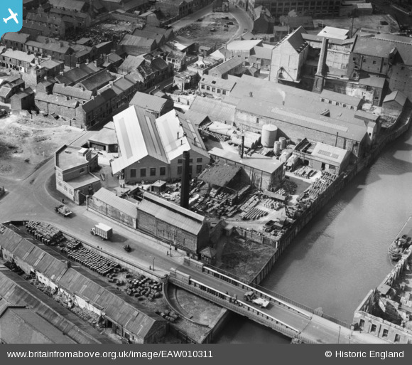
The photographs, on the left above, from Britain from Above are of the the Swan Flour Mills, Sculcoates Bridge and environs, Kingston upon Hull, 1937. and the two on the right are of the John M Hamilton & Co Ltd Sculcoates Bridge Works, Kingston upon Hull, 1947.
Rich and Lou Duffy-Howard
If you’ve enjoyed the post, we’d be delighted if you’d subscribe to our blog. It’s free and you can do so by entering your email below: