The railway swing-bridge over the River Ouse at Goole was designed by Sir William Armstrong and opened in 1869. Its Grade II listed and has a couple of different names: Hook Bridge (if you come from Hook) and the Skelton Viaduct (if you live in Skelton) but if you’re on a train it’s more than likely the railway swing-bridge over the River Ouse at Goole.
Following our Goole by Barge exhibition at Goole Museum, Lou and I were delighted to be invited to visit the railway swing-bridge over the River Ouse at Goole and photograph it as part of the repair and refurbishment project with Network Rail in partnership with Amco Giffen and Goole Museum.
We met engineer Rob Sellers who gave us a guided tour of the engine room and explained the workings and complexities and challenges of repairing and refurbishing a 155 year old hydraulically powered and Grade II listed railway swing-bridge. The locking bolts, lifting gear and cylinder mechanisms had become unreliable – as the existing system had been operational since 1868 – see the original diagrams in the plate below. It was showing signs of wear, so upgrades were required to keep the bridge operational for another 155 years or so.

Amco Giffen engineer Rob Sellers has provided the text and commentary that explains what’s going on in the photographs below and where they link to the original design diagrams published in 1869.
Photographs by Richard Duffy-Howard with additional photo’s by Rob Sellers, Plates, William Armstrong. Click on each image to enlarge.

Photo 1 – In the foreground is one or the two original Turning Engines that was commissioned in 1868 as it’s still in operational use. Its associated open gear box which steps up the torque can be seen behind, and the Rollers which allow the swing span to rotate can be seen above.

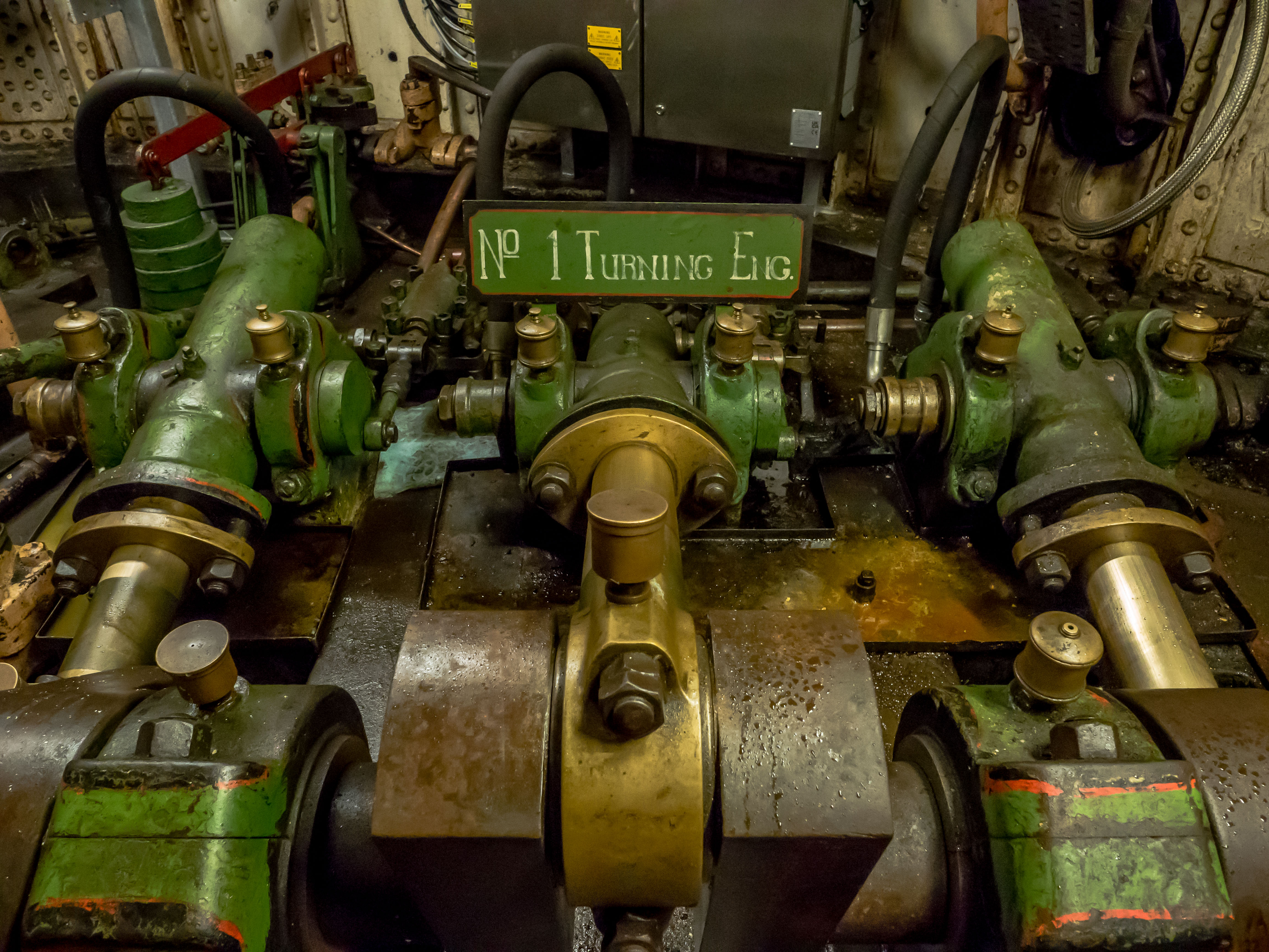

Photo 2 – Original Turning Engine No.1 dating from 1868 (Plate 23 and Item K in Plate 20, Fig. 7 & Plate 21, Fig. 8).

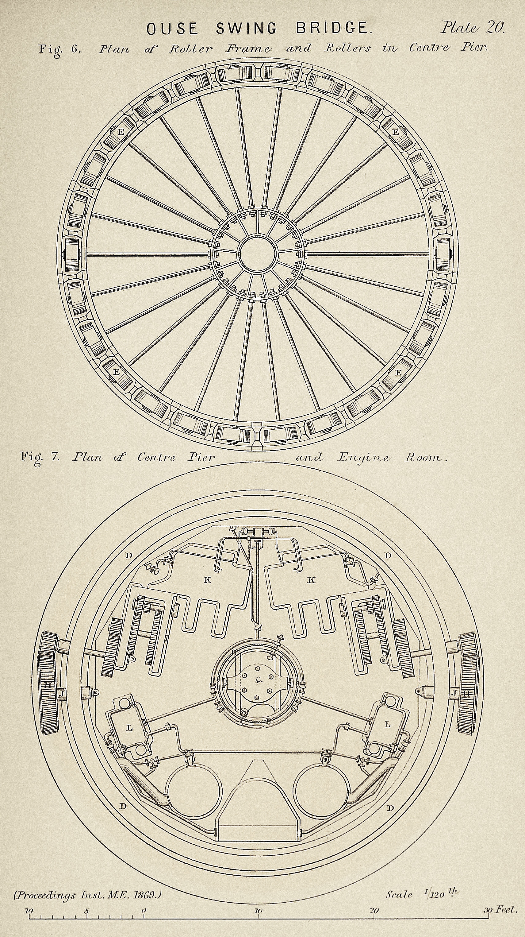
Photo 3 – One of the two original Three-Throw Pumps. (Item L in Plate 20, Fig. 7) that recharges the Accumulator that provide the hydraulic power (pressurised oil) to the engines and bridge jacks and associated equipment.
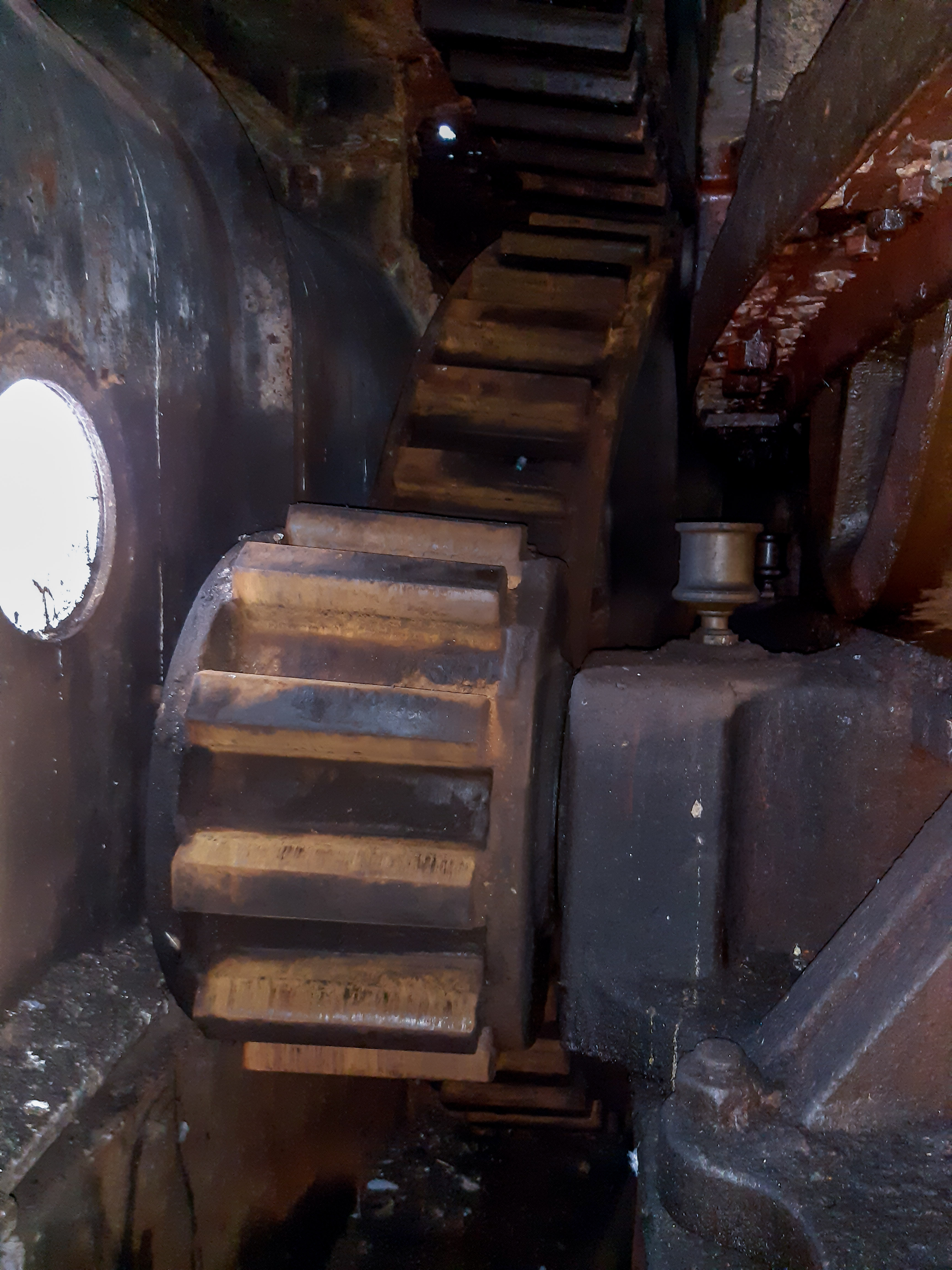

Photo 4 – One of the two open sets of gearing that steps up the torque between the Turning Engines and the final Pinion Gear and Drive Wheels that are exterior to the engine room that operate against the rack on the swing part of the bridge.
Photo 4a – I have added an additional photo (above left) showing one of the two pairs of the final Pinion Gear and Drive Wheel that are exterior to the engine room that operate against the rack on the swing part of the bridge (Item H in Plate 20, Fig. 7 and Item G in Plate 21, Fig. 8).
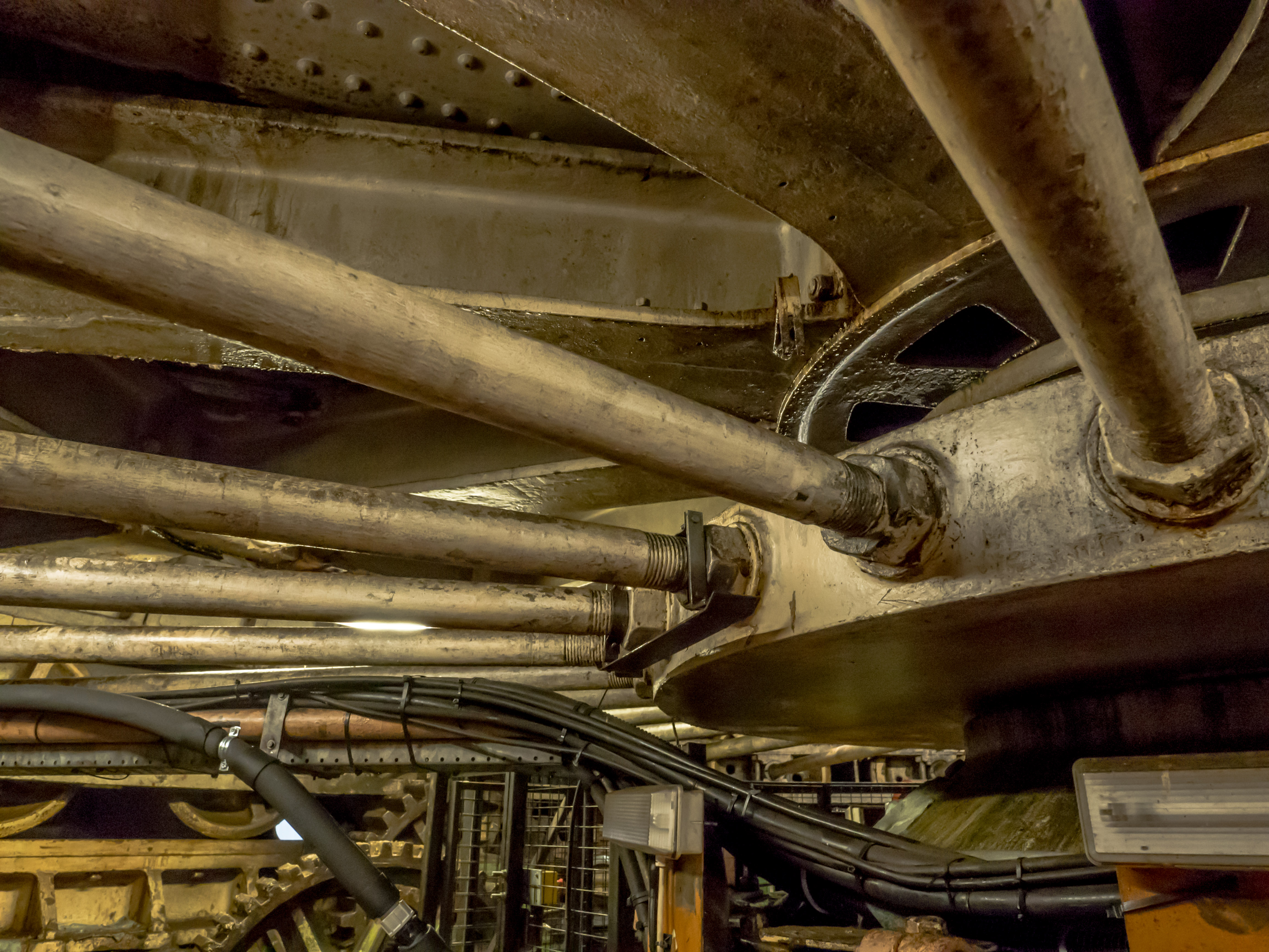
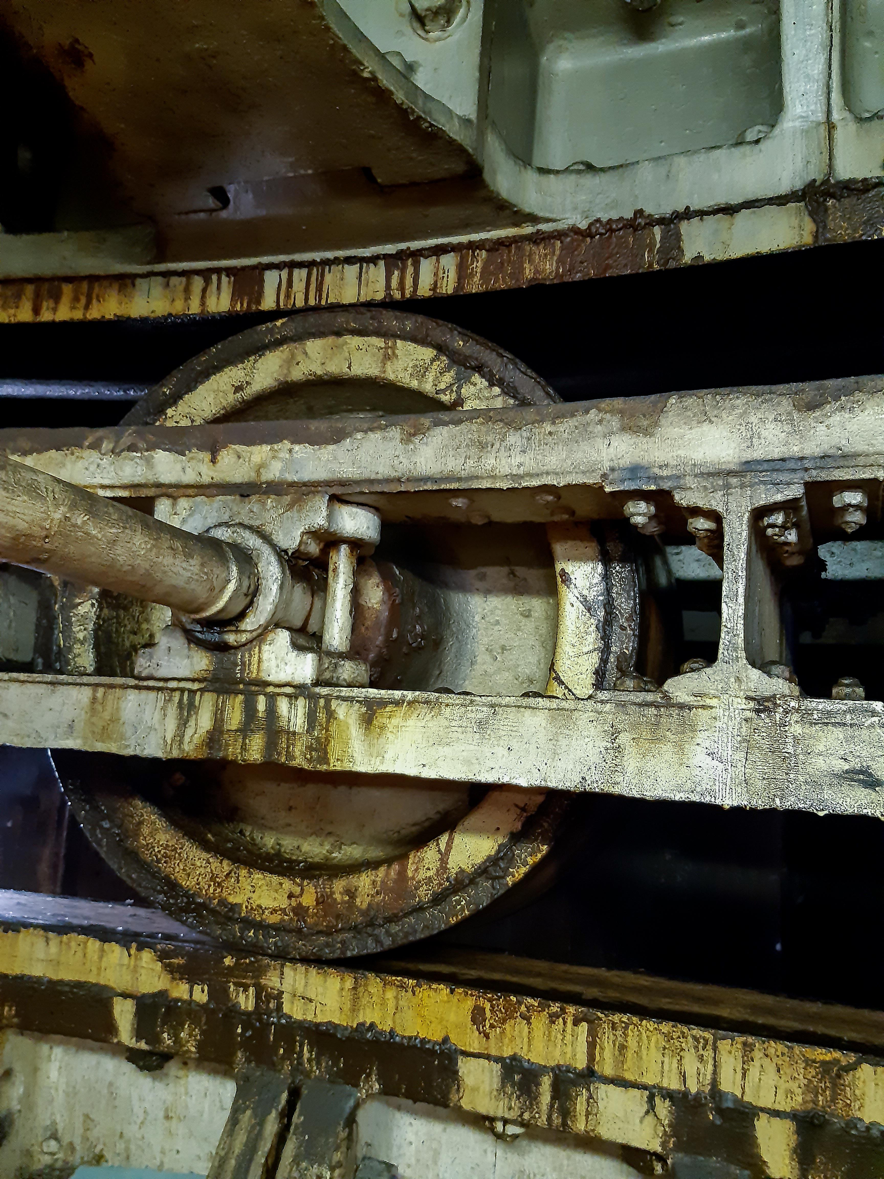
Photo 5 – Showing the Roller Frame, that is located centrally by the Accumulator housing, and locates the 26No Rollers around its circumference. The rotating bridge deck, which rotates at twice the speed and angle of the Roller Frame can be seen above. See Plate 20 Fig. 6.
Photo 5a – I have added an additional photo (above right) showing one of the 26No Rollers. Each roller is 3 feet in diameter with a tread width of 14 inches. The whole of the 76m long swing span is balanced on and fully supported by these rollers when the bridge is being rotated. As can be seen in Plate 21 Fig. 8, the rollers (Items E) are bevelled to match an identical bevel on the upper and lower roller plates. The angle of the bevel being such that the rollers naturally roll the exact curve of the roller paths, eliminating skidding and wear.

Photo 6 – One of the two Lister Diesel Engines from the 1920’s which currently drive the Three-Throw Pumps (that replaced the original steam boiler).

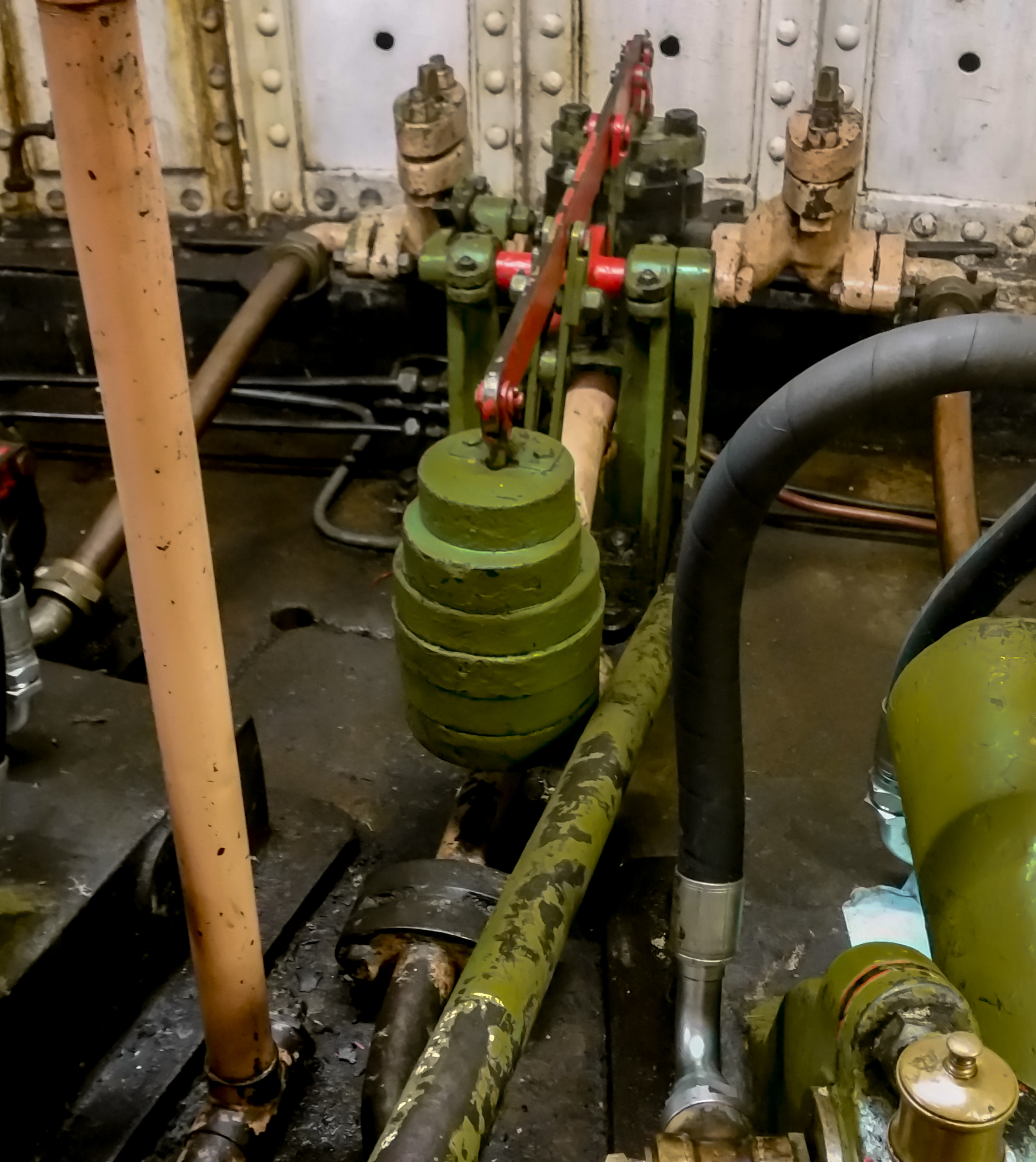
Photo 7 – (I have attached another photo 7a above right, better showing this valve). The original engine control valve which controls either of the two original engines. It is operated only by small longitudinal movements of the green control rod. The initial movement of this rod in one direction initially operates a valve, sending pressurised oil from the accumulator to a separate valve which selects the engine direction, forward or reverse. Continued movement of the rod in the same direction then opens the main feed valve to the engine cylinders allowing progressively more flow of pressurised oil to the engine cylinders, thereby increasing the power.
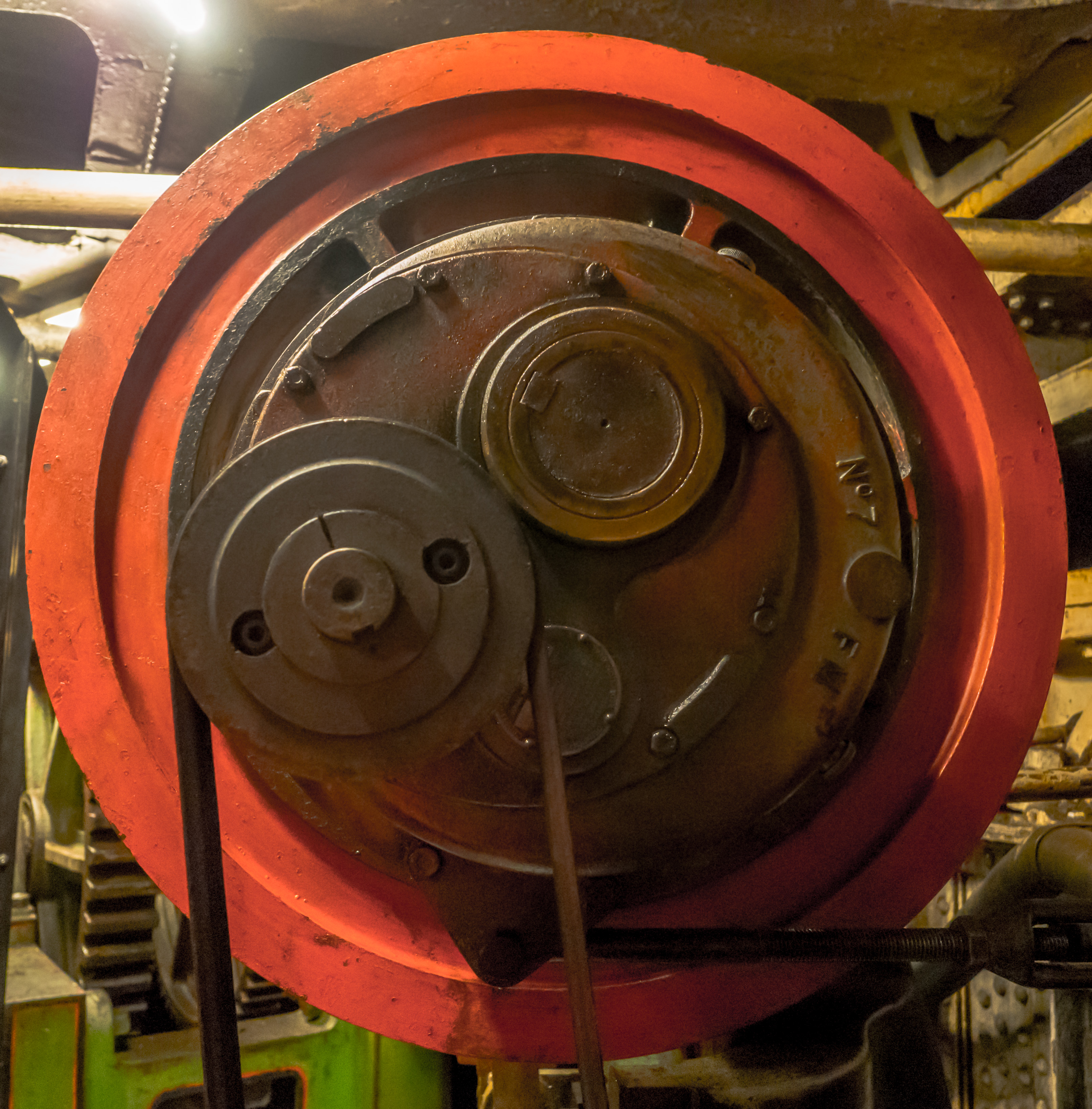

Photo 8 – Above left and as Photo 3 – one of the two original Three-Throw Pumps – but showing here the additional drive coupling added when the steam boilers were replaced by the Lister Diesel Engines in the 1920s.
Photo 9 – Above right – the original Manufacturers Name Plate of the bridges operating equipment that is mounted in the Engine Room on the central accumulator housing. The Pressure Gauge is still operational.
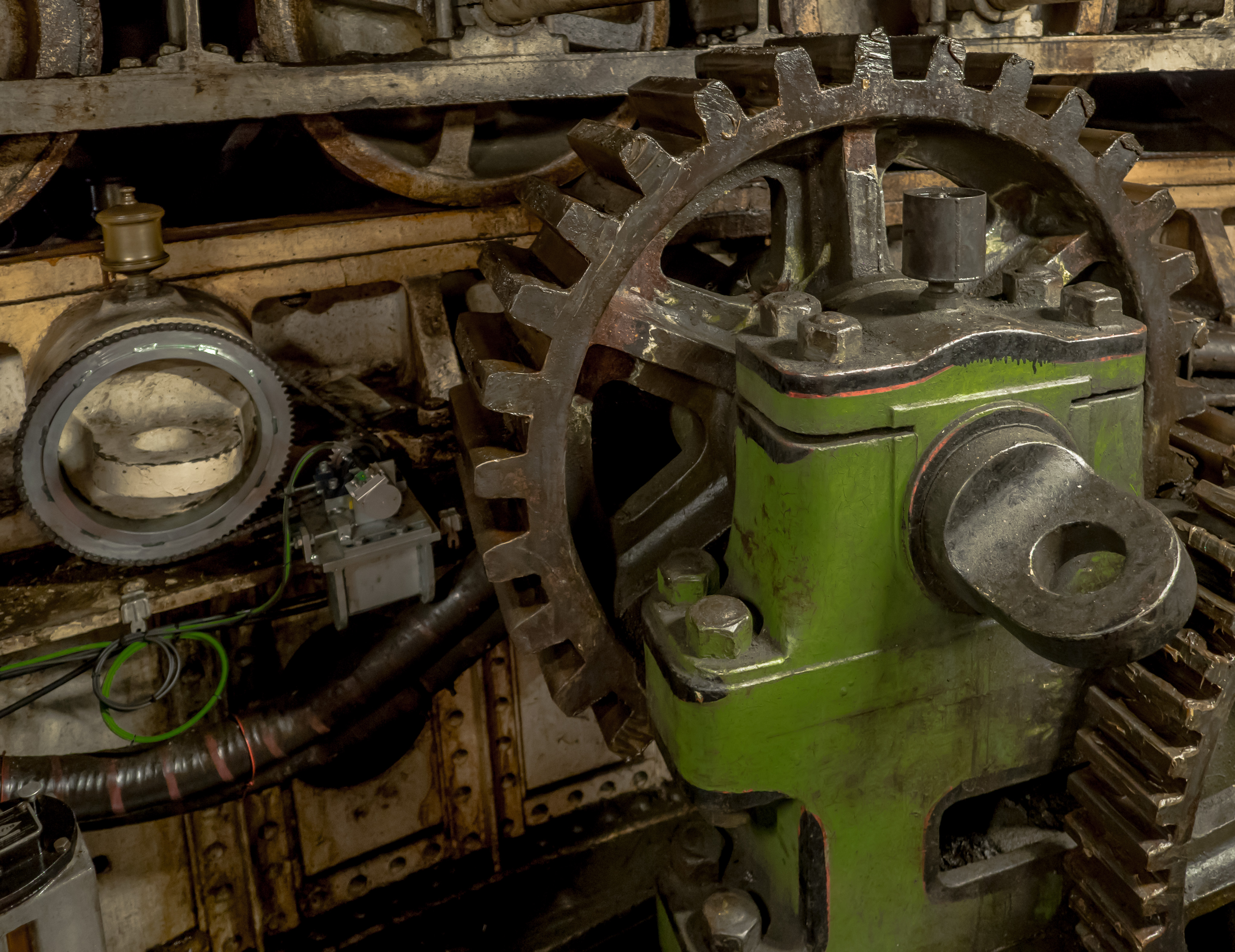
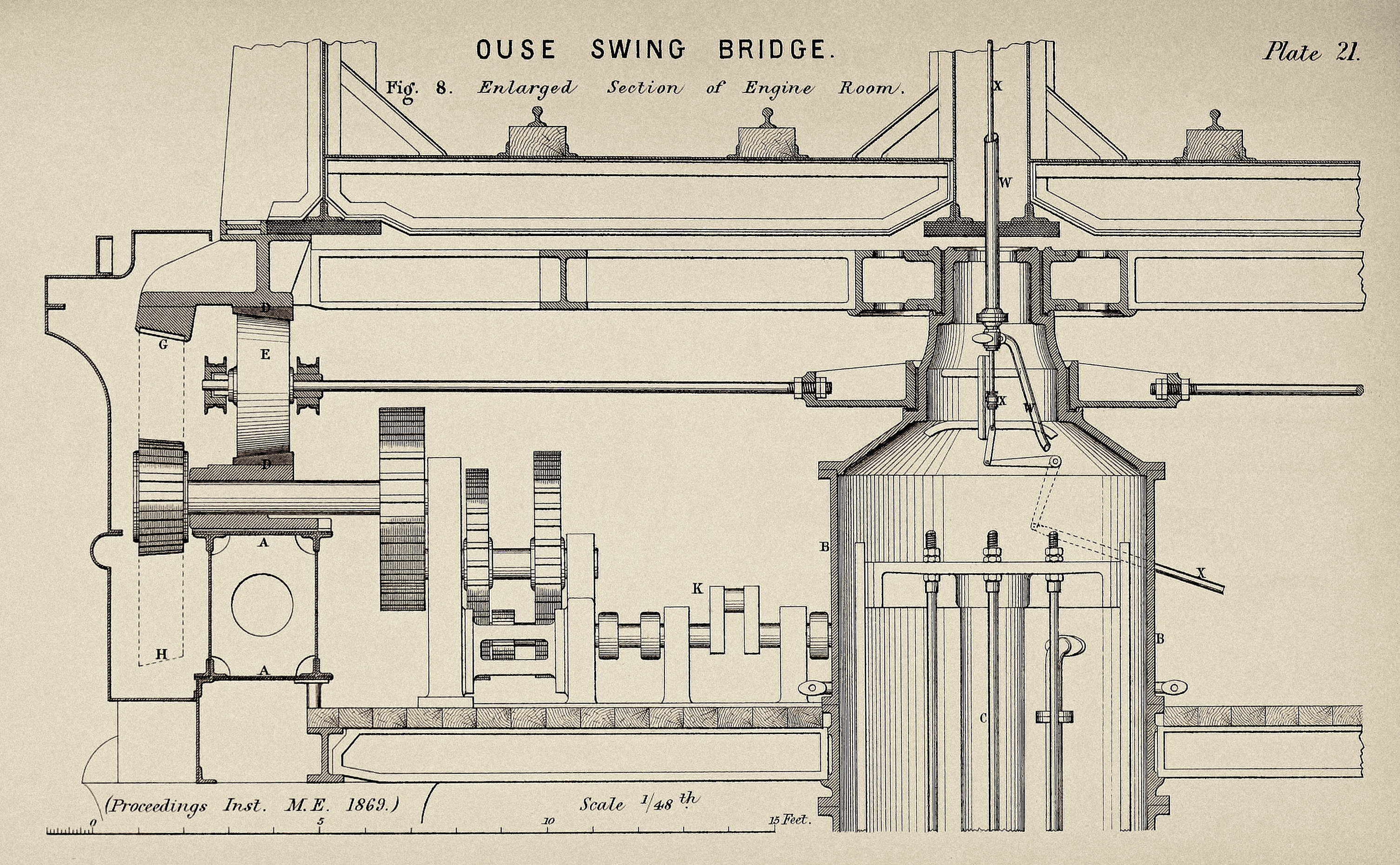
Photo 10 – The final drive shaft of the open gear box passing through the structural beam supporting the roller path to the exterior drive pinion. (See Plate 21, section in Fig 8). The modern miniature toothed gear mounted on the stub end of the shaft on which the exterior drive wheel is mounted (Item J in Plate 20, fig. 7 & Item H in Plate 21, Fig. 8) was installed in 2023 as part of the refurbished works.


Photos 12a, 12b &12c – The Replacement Accumulator installed in the late 1890’s on the centre jetty to replace the original accumulator. It is reported to have been previously in use at Hull Docks prior to it being installed here to replace the original accumulator that failed – and which could not be replaced due to its location central to the engine room (See Plate 19, Fig. 5 & Plate 20, Fig. 8).
The Plates above are taken from the proceedings of the committee meeting of the Institution of Mechanical Engineers, chaired by William Armstrong in 1869. The full text of the meeting along with all of the plates referenced are published here: https://openbridgeshull.com/2025/03/23/railway-swing-bridge-over-the-ouse-at-goole-1869/
This is the second of two posts documenting our visit, the first is at this link: https://openbridgeshull.com/2025/03/26/railway-swing-bridge-over-the-ouse-at-goole-2023/
Thanks to Alex Ombler at Goole Museum, Rob Sellers at Amco Giffen and Network Rail for making it happen.
Rich and Lou Duffy-Howard
If you’ve enjoyed the post, we’d be delighted if you’d subscribe to our blog, it’s free and you can do so below: